
Thursday, October 27, 2011

Wednesday, October 26, 2011
Engine Reflection
Cylinder Head
An inspection of a cylinder head begins with a visual examination, searching for signs associated with wear e.g warping, cracks, chips, deformation etc, followed by a number of measuring tasks to determine wear tolerances.
Cylinder Head Warpage is measured using a straight edge and a feeler gauge. The straight edge is held against the machined surface and a feeler gauge is fitted were possible. If a measurement is able to be taken this measurment is compared with manufacturers tolerances. If warpage is too great then the surface will need to be machined again.

Valve Stems are visualy checked (Stretching, bending, erosion, wear marks) as well as measured. These are measured using the same process as when measuring the guide bore.
Stem to Guide clearance is measured by comparing the two previous measurements. Subtract the valve stem width from the guide measurements and you will be left with the stem to guide clearance.
Valve seats are measured for angle, width and finish. These measurements are compared with manufacturers specifications and if need, reseated.
Valve spring squareness is measured using a surface plate and engineers square. A feeler gauge is used to measure how far off sqaure the spring is. This measurement is compared with manufacturers tolerances and replaced if need be. If a spring is not square this is a sign of wear.

Valve spring installed height is the measurement taken from the spring seat to the retainer. This is done without the spring in place. Remeber to account for the VSI(Valve spring insert). This measurement is used with a spring pressure tester to determine spring tension.
Spring Tension. When using a spring pressure tester the spring is put in place and would down untill it is the same length as when installed (Spring installed height). As the spring is wound down it pushes in the base plate giving a pressure reading. Spring tension can be increased or decreased by adding VSI however remember that ther must always be 1 VSI per spring. All springs should be within 5kg of each other.
Good Practise is to check all nuts, stud, bolts, threads as you work and replace or recondition where needed.
Frost plugs should also be checked for leaking, deformation and corrosion.
Cam Lobes are measured to determine the lift of each lobe. The are measured at the widest point and the narrowest point(where the wear begins). This measurement allows us to work out how much travell the valve will have and when it start to open and close.
Bearing Journals are also measured. From these mesurement we can determine Taper and Ovality.

Runout of the crankshaft is measured usind a DTI gauge(Dail test indicator) and a mircometer. A measurement is taken usinng a DTI gauge then converted to a metric reading using a mircometer. This measurement is then compared with manufacturers tolerances.
Plasti-gauge is used to measure oil clearances in various parts of the engine. For example when measuring the oil clearance of a crank/cam journal a slither of plasti is placed in the journal and then as the bearing cap is tightened it squashes down. Once the cap is removed the thickness of the plasti-gauge is measured to determine clearance.
Bearing Journals are also measured. From these mesurement we can determine Taper and Ovality.

Runout of the crankshaft is measured usind a DTI gauge(Dail test indicator) and a mircometer. A measurement is taken usinng a DTI gauge then converted to a metric reading using a mircometer. This measurement is then compared with manufacturers tolerances.
Plasti-gauge is used to measure oil clearances in various parts of the engine. For example when measuring the oil clearance of a crank/cam journal a slither of plasti is placed in the journal and then as the bearing cap is tightened it squashes down. Once the cap is removed the thickness of the plasti-gauge is measured to determine clearance.
Short block & Outboard

The Piston is measured along its thrust sides. Aprox 10-15mm from bottom of skirt. This measurement is done with a micrometer and then compared to mannufacturers specs to determine if/how much wear has occured. A visual inspection is also done.
Cylinder Bore is measured the same was as the valve guide, however a bore gauge is used. This measurement will allow us to calculate Taper and Ovality of the bore.
Piston to Bore clearance is determined using measuremennts of the piston and bore. Subtract the width of the piston from the bore and this will give you the clearance.
 Piston ring side clearance is measured using a feeler gauge placed just above the ring while in place. This is measured to ensure that the ring has enough clearance after the ring has expanded due to heat. The measurement is then compared with manufacturers specifications.
Connecting rods are measured for bend and twist. This is done using an engineers square and a feeler guage. if deformation is minor then the rod may be rectified rather than replaced.

Note: If diagonal wear marks are present down the piston this could be a sign of a deformed Con Rod.
Main bearing & Big end journals, as with Cam journals, are measured using a micrometer. Multiple measurements are taken of each journal to determine Taper and Ovality. Measurements are compared with manufacturers specification to determine wether replacement is needed.
Crankshaft Deflection/Run out is measured usinng the same tools and processes as when measuring Cam shaft runout.
Cylinder block face is checked for warpage, erosion, cracks, corrosion. Using a stright edge and a feeler gauge the cylinder block face is measured like the cylinder head face.
Timing gear such as belts, chains, gears, sprockets are all checked for damage annd wear.
Water pumps are checked for corrosion, damage, leakage and flow rate.
Oil pumps clearances are measured using a feeler gauge and the reading is then compared to manufacturers specifications to determine condition. Gears are check for damage and wear.
This excersize of dismantling, measuring and reassembling an outboard, short block, 2-stroke and cylinder head has given me practical and measuring experience. Although there is alot of measuring involved a big part of this process is visual and I feel this excersize has given me the ability to identify wear and damage.
Sunday, October 2, 2011
Gearbox Reflection
Gearbox Reflection
The past few weeks have seen us dismantling, assesing and reassembling automotive and marine transmissions. We have covered a variety of transmissions; Toyota 4k manual gearbox, Outboard gearbox, Sturn drive and hydrolic marine gearbox.
 |
| Penta Hydrolic Gearbox |
During this excersize I gained first hand experience with gearboxes. I feel it is alot easier to understand how the gearbox works when your able to see how the parts move within the box. It also helped illistrate the importance of following a dismantling proccedure and during reassembly, the importance of fitting each part correctly.
 Visual inspection is a major part of gearbox reconditioning, this excersize has taught me how to identify damage and wear. For example we check the case hardening on all gearbox components, if the hardened surface has any nicks or chips then this part is destined to fail. Gears are checked for wear, damaged teeth and excess play. Bearings are also checked, it is important to ensure that all bearings are running on hardened surfaces.
The synchromesh unit is very important. Ensure all parts are present and check for damage and wear. It is importannt that the baulk ring in correctly fitted or it will not synchronise the gear speeds.

Runout is measured on all shafts. Housings are measure for distortion. Oil pump clearances are checked agaist specifications. The bevel gear that drives the propellor is set to ensure correct contact.

I also learnt how to calculate a gear ratio.
Most important when dismantling an automotive gearbox... Dont loose the tic tac's!!!


Saturday, October 1, 2011
Gearboxes
Gearboxes
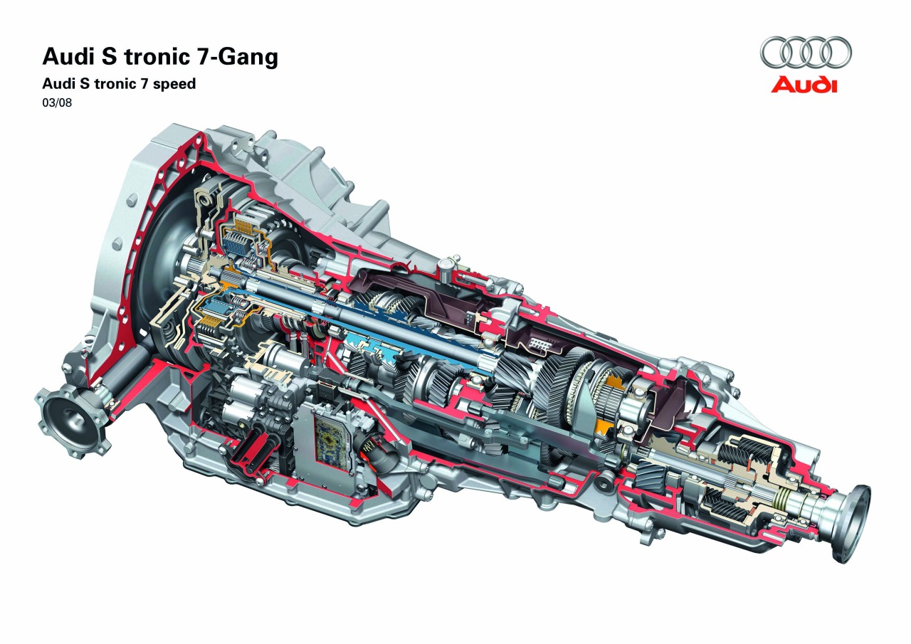
What type of gears are used for reverse in a manual gearbox?
'Spur' Cut or 'Straight' cut gears have teeth projecting radially. These are used for the reverse driver,driven and idler gear. Spur cut gears are generally low speed gears and can be noisy. Reverse gears are not in constant mesh and do not have any synchro mechanism, therefore the output shaft must not be turning when reverse is engaged. This is a very simple type of gear and is only used on shafts that are parallel to each other.

What type of gears are used for forwards gears in a manual gearbox?
Foward gears are constant mesh gears.This means they are always contacting each other. Forward gears are 'Helical' cut, this is when the teeth on the gear are angled. Helical gears are used for high speed applications and transmission of large power outputs. Helical cut gears are not as noisy as spur cut gears.


What is the purpose of a synchro mesh unit and how does it work?
The purpose of synchro unit is to engage a free spinning constant mesh gear to the output shaft. A synchro mesh unit consists of a Baulk ring, Synchro hub and Slider(Dog Clutch). As a gear is selected the slider pushes the baulk ring against the chosen gear, using friction the baulk ring synchronises(speeds up or slows down) the gear speed with the input shaft. As the two gear speeds synchronise the slider moves to engage the free spinnning gear with the output shaft.


The purpose of the baulk ring is to synchronise the gear with the output shaft. Also to stop the slider from engaging the gear before it is synchronised.
How do you check a Baulk ring for seviceability?
When checking a baulk ring for servicability you must check the dog teeth for wear. You must also check the ridges inside the ring that keep the ring lubricated while synchronising the gears.
A variety of bearings are used in different gearboxes. But most common are Roller, Thrust bearing, Needle roller and Caged roller bearings. Different bearings are used for different applications depending on the load that it will be placed under.

Give an explanation of a Gear Ratio.
A gear ratio relates to the speed at which two gears turn. A 1:1 gear ratio has a drive gear that turns the driven gear at the same speed, for example a gear with 25 teeth driving a a gear with 25 teeth. A 2:1 ratio would be a gear with 50 teeth driving a gear with 25 teeth. It is possable to have a ratio involving more than two gears.

Wednesday, July 6, 2011
2 Stroke Engines
2 Stroke Engines
The difference between them is the amount of strokes needed to complete the four stages of an engine cycle. Intake, Compression, Ignition/Power, Exhaust. A 2 stroke does this in only two strokes or revolutions of the engine. A four stroke does this in four revolutions.

A diesel 2 stroke has a wet sump and is more like a four stroke in respect to the fact that everything happens above the piston. All diesel 2 stroke engines are artificially aspirated using either a turbo or supercharger. As the piston moves down the bore the exhaust and intake valves are exposed. As the exhaust evacuates the combustion chamber pressure changes allow the inlet reed valve to open and the turbo forces fresh air into the chamber. As the piston starts to rise the inlet and exhaust ports close and pressure begins to build. As the air is compressed its temperature rises.Just before T.D.C the diesel fuel is injected and ignites forcing the piston down. This cycle is repeated.
Explain how a two stroke engine works?
This engine is designed to complete the four stages of the engine cycle in two strokes. It works by drawing an Fuel/Air/Oil mixture into the crankcase(Pre-combustion chamber) as the piston moves up the cylinder, at the same time the Fuel/Air/Oil mixture above the piston is being compressed. As the piston reaches T.D.C the mixture above the piston is ignited, forcing the piston downward exposing the exhaust and transfer port. As the piston moves down the cylinder pressure pushes the reed valve on the inlet port shut and starts to build pressure in the pre-combustion chamber. As the tranfer port opens the Fuel/Air/Oil mixture flows from the pre-combustion chamber to the combustion chamber. The shape of the top of the piston causes the mixture to swirl as it enters, this helps expell exhaust fumes and reduces fresh mixture leaving the chamber before combustion.

What is happening below and above the piston?
 Above the piston we have Compression, Ignition and Transfer/Exhaust of the fuel.
Below the piston we have Intake, Pre-compression and Tranfer.
Note - As the Fuel/Air/Oil mixture is compressed it lubricates the system.
Explain what is meant, by scavenging when applied to 2 stroke SI engines?
This is the proccess of pushing the exhaust gases out and drawing the new mixture in. The scavenging effect can be helped by making sure the flow of gases through the system is uninterupted.
 Why must roller and ball race bearings be used on 2 stroke SI engine crankshafts?
2 Stroke engines are lubricated using oil in the fuel. Because of this we use open bearings such as roller/ball race bearings. As the mixture is compressed the oil within the fuel mixture works its way through the bearings lubricating them. If a sealed type bearing was used then the oil would not enter the bearing when compressed.
Why are rollers caged in crankshaft bearings?
 Caged roller bearings are used because the cage holds each roller in place stopping them from bunching up and unevenly distributing the load.
 Why must ‘split’ type bearings be used on one piece crankshafts?
If split type bearings were not used on a one peice crankcshaft then it would be impossible to service/remove the bearing should it wear out. Split type bearings can be fitted around the crankshaft.
Why do we have pins between the piston ring gaps on a 2 stroke?
We have pins between the ring gaps to locate the piston rings. As the rings pass over the valves friction can cause them to move, these pins keep the rings from moveing.How does a reed valve work on a two stroke?
 This is basicly a one way valve. It opens as pressure increases on one side and closes as pressure builds on the opposite side. This is used on the intake side of a 2 stroke. As the piston move up the cylinder the reed valve opens allowing mixture to enter. As the piston move down and compresses the mixture it forces the valve shut.
A Reed valve can be checked by visual inspection, the reed valve must completely close. You can also blow againsted the valve from each direction to make sure the valve acts as it should.
 |
Ovality - This refers to the deformation of a circular object to an oval. Wear on the thrust sides of a piston can cause it to become slightly oval.
Taper - For example wear on the cylinder wall can cause a taper or slope of the wall. This wear occurs on the thrust sides of the piston. A tapered bearing has a cone shape.
How does the piston rings seal in the bore?
As the piston rises pressure above the piston increases. This pressure pushes down past the piston, as it reaches the piston ring grove the pressure acts on the ring pushing it outward againsted the cylinder wall. Sealing the bore.
 |
| Measuring Side clearance |
Explain these terms:
Groove depth - This is the depth of the groove the piston ring sits in. this is measured with a Feeler gauge.
Side clearance - This is the clearance between the piston ring and the side of the ring groove. This is measured using a Feeler gauge.
End gap - Place the ring in the bore. As it rests level in the bore there is a small gap, this is the end gap. We measure this with a Feeler gauge.
 |
| B - Measuring end gap |
What do the following terms mean:
Mechanical Efficiency - This is a measure of effectiveness of a machine. A low friction machine would have a higher mechanical efficiency that a machine with high friction or resistance.
Thermal Efficiency - This refers to a dimensionless measure of performance in a device that uses thermal energy
Volumetric Efficiency - This refers to the engines ability to move a fuel/air/oil charge into and out of the cylinder. Artificialy aspirated or forced induction engines would operated above 100% efficiency.
List 2 methods of lubricating the internal parts of 2 stroke S.I. engines?
Lubrication of 2 stroke internal parts is done by introducing oil into the fuel.
This can be done two ways;
The oil can be added directly to the mixture in the fuel tank.
The oil is injected into the intake manifold and mixes during intake. When not using pre-mixed fuel there is a small pump that runs off the crankshaft. This increases oil delivery as the engine speed increases.
What happens if the piston ring gap is too big?
If the piston ring gap is too big then the piston ring will not seal when it expands. This will drop compression causing power loss. This could also cause blow back through the carburettor.
What happens if the piston ring gap is too small?
If a piston ring gap is too small it means that the piston ring cannot retract and may seize or cause excessive wear.
References
http://www.wikipedia.com/
http://www.google.com/
Ed May Vol 1
Ed May Vol 2
E-learning/ Blogging
My Opinion
Tuesday, June 7, 2011
Marine Fuel Systems Part 2
Marine Fuel Injection
Who invented Fuel injection and why?
The first use of direct petrol injection was in 1925 on the Hasselman engine invented by Swedish engineer Jonas Hasselman. This was a hybrid engine designed to run on both Petrol and Diesel, it was used in busses and heavy trucks in the 1920-1930s. Gasoline injection systems were designed during world war 2 for aircraft because of its greater imunity to wildly changing g-forces.
How does a single and multi injection system work?
 Single Injection system - This is when a single injector is fitted just behind the throttle body. As the air passes the throttle butterfly the injector sprays a mist of fuel which mixes with the air as it is drawn into the combustion chamber. The MAF, MAP, MAT sensors all assist the ECU in maintaining a steady fuel mixture.
 Multi Injection system - This refers to a system were the fuel is injected at multiple points. Usually there will be an injector located at the bottom of the inlet manifold, just above the intake valve on each cyclinder. This system produces a better Air/fuel mix and allows the inlet manifold to be designed to maximise air flow.
What does EFI stand for?
EFI stands for Electronic Fuel Injection. This is a name that refers to a Petrol internal combustion engine that is electronnicaly controled and is fuel injected as apposed to Carburetted.
 What is an ECU?
ECU stands for Electronnic Control Unit or Engine Control Unit. This is like the brain of the engine. Signals from various engine sensors are sent to this unit, the ECU then sends signals to components such as the injectors or intake butterflies. Through operations such as that the ECU maintains control of the engine.
(MAF) Mass Air Flow sensor?
This is the sensor that is used to measure the amont of air entering the engine. The information gathered by this sensor is sent to the ECU and allows it to adjust the fuel delivery as necessary. Two common sensors are the Hotwire sensor and Vane meter. These sensors to need input from additional sensors to be accurate. Other less common sensors are the Coldwire sensor, Karmnan Vortex sensor and the Membrane sensor.

Hotwire Sensor
The hot wire sensor works by passing a current through a wire suspended in the air intake. As the wire heats up the electrical ressistance increases, limiting electrical current. As air passes over the wire the heat reduces allowing more current to pass throught the circute. These changes in current are converted into voltage which is sent to the ECU.
Vane Sensor
The Vane Airflow sensor is a spring loaded airflap that is attached to a variable resistor. As air flow increases the flap opens and the resistor moves. As the angle of the resistor varys so does the voltage being sent to the ECU. Some draw backs such as:

- Need to be oreinted in respect to gravity
- Electrical and Mechanical contacts can wear
(MAT) Manifold Air Temperature sensor?
This sensor is a thermistor, a resistor that reduces resistance with temperature increase. It is screwed into the intake manifold to measure manifold air temperature and relay it to the ECU.
(MAP) Manifold Absolute Pressure sensor?
This sensor measures manifold pressure. It is responsive to vacuum and barometric pressure. Air/Fuel ratio, Ignition timing an Idle speed can all be modified by the ECU as a result of the MAP sensors signal.
 |
| Blue:Throttle Position sensor Red: MAP sensor |
Throttle Position sensor
This sensor is used to measure the position of the throttle butterfly within the throttle body. This sensor is usually located on butterfly spindle and directly monitor the valve position. The sensor is a variable ressistor therefore will send a different signal depending on throttle position.
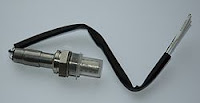
Oxygen/Lambda sensor?
This sensor is used to measure the Oxygen within the exhaust fumes. By determining the Oxygen level we are able to establish in real time if the engine is running rich or lean. This also helps with emissions.
Engine Temperature sensor?
Engine Temperature sensor?
The engine temperature sensor is located in the engine coolant. Measuring the temperature of the coolant is a good way to determine the engine temperature.
Cam & Crankshaft Position sensors?
This sensor is used to determine the (RPM) rotational speed at which the Cam/Crankshaft is moving and the Cam/Crankshaft position. This sensor will consist of a rotating part, generaly a disc with magnet, and a static part. The actual sensor. This sensor is not always located directly on the Cam/Crankshaft, it can also be run off a belt or gear. The signal from both the Cam Position sensor and the Crank Position sensor alow the ECU to adjust the ignition timing, idle annd acceleration.
Idle air supply.
When the engine is idleing the throttle butterfly is closed and allows very little air past. So air passages are provided that bypass the throttle valve to allow air into the intake during idle. These air passages can sometimes be adjusted with a screw on the throttle body.

The throttle body is the housing that holds the throttle assembly and sensors. This assembly controls the air flow to the engine and responds to the accelerator pedal.
What is the Plenum chamber?
The Plenum chamber is used to distribute air flow between cylinders. Air flows through the throttle body into the plenum chamber (often moulded and surfaced for better flow and distribution) then through the intake manifold, mixing with the fuel just before entering the cylinder.

What are Injectors?
Injectors are the final piece to the fuel system puzzle. Located in the intake manifold just about the intake valve, the injectors deliver a specific amount of fuel to each cylinder. Signals from the ECU tell the injectors when to open and how long to open for.
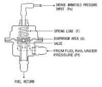
What is a Fuel pressure regulator?
This is a metal housed, spring-loaded diapragm used to regulate the pressure in the fuel system. Regulating pressure is usually around 250kpa and is set durinng manufacture. Pressure is determined by strength of the spring. the chamber above the diaphragm is connected to the intake manifold and so subject to vacuum. When excess pressure builds up the diaphragm lifts the valve and returns extra fuel to the fuel tank.

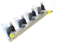
What is a Fuel rail?
A fuel rail runs along the engine and delivers fuel directly to the injectors. Fuel is delivered to the fuel rail via fuel lines from the fuel pump. The fuel rail is kept at pressure and regulated by the pressure regulator.

References
Ed May Vol 1
Ed May Vol 2
Subscribe to:
Posts (Atom)