Tuesday, June 7, 2011

Marine Fuel Systems Part 2

Marine Fuel Injection
Who invented Fuel injection and why?
The first use of direct petrol injection was in 1925 on the Hasselman engine invented by Swedish engineer Jonas Hasselman. This was a hybrid engine designed to run on both Petrol and Diesel, it was used in busses and heavy trucks in the 1920-1930s. Gasoline injection systems were designed during world war 2 for aircraft because of its greater imunity to wildly changing g-forces.
How does a single and multi injection system work?
Single Injection system - This is when a single injector is fitted just behind the throttle body. As the air passes the throttle butterfly the injector sprays a mist of fuel which mixes with the air as it is drawn into the combustion chamber. The MAF, MAP, MAT sensors all assist the ECU in maintaining a steady fuel mixture.
Multi Injection system - This refers to a system were the fuel is injected at multiple points. Usually there will be an injector located at the bottom of the inlet manifold, just above the intake valve on each cyclinder. This system produces a better Air/fuel mix and allows the inlet manifold to be designed to maximise air flow.

What does EFI stand for?
EFI stands for Electronic Fuel Injection. This is a name that refers to a Petrol internal combustion engine that is electronnicaly controled and is fuel injected as apposed to Carburetted.

What is an ECU?
ECU stands for Electronnic Control Unit or Engine Control Unit. This is like the brain of the engine. Signals from various engine sensors are sent to this unit, the ECU then sends signals to components such as the injectors or intake butterflies. Through operations such as that the ECU maintains control of the engine.


(MAF) Mass Air Flow sensor?
This is the sensor that is used to measure the amont of air entering the engine. The information gathered by this sensor is sent to the ECU and allows it to adjust the fuel delivery as necessary. Two common sensors are the Hotwire sensor and Vane meter. These sensors to need input from additional sensors to be accurate. Other less common sensors are the Coldwire sensor, Karmnan Vortex sensor and the Membrane sensor.

Hotwire Sensor
The hot wire sensor works by passing a current through a wire suspended in the air intake. As the wire heats up the electrical ressistance increases, limiting electrical current. As air passes over the wire the heat reduces allowing more current to pass throught the circute. These changes in current are converted into voltage which is sent to the ECU.
Vane Sensor
The Vane Airflow sensor is a spring loaded airflap that is attached to a variable resistor. As air flow increases the flap opens and the resistor moves. As the angle of the resistor varys so does the voltage being sent to the ECU. Some draw backs such as:
 - Can restrict airflow
 - Need to be oreinted in respect to gravity
 - Electrical and Mechanical contacts can wear


(MAT) Manifold Air Temperature sensor?
This sensor is a thermistor, a resistor that reduces resistance with temperature increase. It is screwed into the intake manifold to measure manifold air temperature and relay it to the ECU.

(MAP) Manifold Absolute Pressure sensor?
This sensor measures manifold pressure. It is responsive to vacuum and barometric pressure. Air/Fuel ratio, Ignition timing an Idle speed can all be modified by the ECU as a result of the MAP sensors signal.
Blue:Throttle Position sensor
Red: MAP sensor

Throttle Position sensor
This sensor is used to measure the position of the throttle butterfly within the throttle body. This sensor is usually located on butterfly spindle and directly monitor the valve position. The sensor is a variable ressistor therefore will send a different signal depending on throttle position.

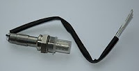
Oxygen/Lambda sensor?
This sensor is used to measure the Oxygen within the exhaust fumes. By determining the Oxygen level we are able to establish in real time if the engine is running rich or lean. This also helps with emissions.
                                                    
Engine Temperature sensor?
The engine temperature sensor is located in the engine coolant. Measuring the temperature of the coolant is a good way to determine the engine temperature.
Cam & Crankshaft Position sensors?
 This sensor is used to determine the (RPM) rotational speed at which the Cam/Crankshaft is moving and the Cam/Crankshaft position. This sensor will consist of a rotating part, generaly a disc with magnet, and a static part. The actual sensor. This sensor is not always located directly on the Cam/Crankshaft, it can also be run off a belt or gear. The signal from both the Cam Position sensor and the Crank Position sensor alow the ECU to adjust the ignition timing, idle annd acceleration.
Idle air supply.
When the engine is idleing the throttle butterfly is closed and allows very little air past. So air passages are provided that bypass the throttle valve to allow air into the intake during idle. These air passages can sometimes be adjusted with a screw on the throttle body.

What is the Throttle body?
The throttle body is the housing that holds the throttle assembly and sensors. This assembly controls the air flow to the engine and responds to the accelerator pedal.

What is the Plenum chamber?
The Plenum chamber is used to distribute air flow between cylinders. Air flows through the throttle body into the plenum chamber (often moulded and surfaced for better flow and distribution) then through the intake manifold, mixing with the fuel just before entering the cylinder.
What are Injectors?
Injectors are the final piece to the fuel system puzzle. Located in the intake manifold just about the intake valve, the injectors deliver a specific amount of fuel to each cylinder. Signals from the ECU tell the injectors when to open and how long to open for.

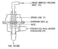
What is a Fuel pressure regulator?
This is a metal housed, spring-loaded diapragm used to regulate the pressure in the fuel system. Regulating pressure is usually around 250kpa and is set durinng manufacture. Pressure is determined by strength of the spring. the chamber above the diaphragm is connected to the intake manifold and so subject to vacuum. When excess pressure builds up the diaphragm lifts the valve and returns extra fuel to the fuel tank.


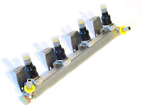
What is a Fuel rail?
A fuel rail runs along the engine and delivers fuel directly to the injectors. Fuel is delivered to the fuel rail via fuel lines from the fuel pump. The fuel rail is kept at pressure and regulated by the pressure regulator.

 References
Ed May Vol 1
Ed May Vol 2

Marine Cooling Systems

Marine Cooling Systems

States of Heat transfer.
Conduction - This is the transfer of heat though direct contact
Convection - This is the transfer of heat from a solid surface to a liquid or gas in motion over it.
Radiation - This is the movement of heat though and empty space.

Indirect Cooling.
Indirect cooling refers to a cooling system where the cooling source does not act directly upon the engine. Air-to-Liquid/Liquid-to-Liquid. One such system uses a raw seawater heat exchanger. The coolant flows through the engine through the core heat exchanger, then radiates out into the seawater flowing through the exchanger and over the core.
Note the cooling fins
Direct Cooling.
Direct cooling is when the cooling source acts directly on the engine. Such as air cooling which moves across blades moulded in the engine block absorbing the radiating heat from the engine. Another system involves raw seawater which is pumped through the engine and out the back of the boat.

What problems can arise in these cooling systems?
Direct cooling- When using a raw seawater system there is always the problem of corrosion. The salt water flowing though the passages of the engine starts to corrode the metal, working its way out. Engines using this sytem usually only last a couple of years as the coolant passages become severly corroded and start to leak coolant.
Indirect cooling- The heat exchanger system spoken about earlier faces the same problems. As raw water flows into the exchanger it is exposed to the corrosive salt within the water. Because of this the exchanger will need to be serviced or possibly repaired on a scheduled basis. Zinc anodes are placed within the exchanger to draw corrosion, these are replaced when serviced. There is also the possiblilty of over heating if flow of the primary coolant stops or is impaired.

What is the purpose of the thermostate?
The purpose of the thermostate is to time circulation of the coolant from the enngine to the radiator. When the thermostate is closed it forces the water to circulate within the engine, when the engine reaches operating temperature the thermostate opens allowing water to flow to the radiator and fresh coolant to circulate.

What is a pressure cap?
This is the cap were coolant is filled. As the engine heats up and the temperature of the coolant increases it expands and raises the pressure within the system. When pressure reaches the threshold the coolant pushes past the cap an into the overflow tank. As the coolant cools down it draw coolant in from the overflow tank in the pressure cap closes.

Why and what is the purpose of a core plug?
A Core or Frost plug is a metal plug in the side of the engine. This hole allows the sand to be removed after casting of the block. When plugged coolant will flow past these holes, if the coolant should ever freeze and expand the pressure will force the plug out and release the pressure without deformation of the block.

How does a heat exchanger work & What is it made of?
A heat exchanger was created as a medium, between the salt water coolant and the engine, to combat excessive engine corosion. An anitfreeze solution is circulated though the engine aborbing excess heat. When the thermostate opens water passes into the central core of the heat exchanger. Raw sea water is pumped through the heat exchanger and as it passes over the core it asborbs the heat from the antifreeze running inside. Anodes are place within the exchanger to help corosion issues.
The heat exchanger is made with various materials such as steel, copper, bronze.

How does a Centrifugal circulating water pump work?
This is an impellor that is driven from its center by an acuating shaft. This is the type of water pump uses on outboard engines. This impellor would usually be found on the gearbox drive shaft.

How does a Raw water pump work?
A raw water pump works the same as a centrifugal circulating pump. It has a central driven impellor, this pump often works via a belt or gear.
Why is it important to lubricate the impellor when fitting from new?
This is important because when the engine starts the impellor will not be covered in water and if not lubricated the implellor will rip. This is lubricated only to resist damage during the first few second of operation.

When refitting impellor what should be done before fitting the housing & Why?
It is imortant to check the woodruff key is in place. This is a small locator lug that is recesed into the shaft that turns the impellor. If the key is not fitted the impellor will not turn and the engine will overheat causing damage.
What is the purpose of an Oil cooler and how does it work?
An oil cooler works similar to the main cooling system, it also has a Liquid-to-Liquid heat exchanger. Oil is pumped through the core of the heat exchanger passing its heat through the metal and out through the raw water pumping past. If using raw water cooling, often different coolers(oil,water) would be laid in succession within one circut.


What is the process of an Intercooler/Aftercooler?
The pupose of this component is to reduce the temperature of the air, that has been compressed by the turbo or supercharger, before it enters the engine. This can be done by directing air across a radiator like component or using a raw water heat exchanger.
Why do we have Inhibitors & Antifreeze?
These are chemical compounds added to our coolant to help increase its boiling temp and lower its freezing temp. The main purpose of Antifreeze is to reduce the risk of engine deformation due to water expansion upon freezing. Antifreeze works to both lower freezing point and raise boiling temperature, it also sticks to the metal helping to prevent corrosion from cavitation.
How do you test Antifreeze?
We have antifreeze tester such as the one in this picture. This will give us a reading of freezing temperature. Also a mixture with high antifreeze content will have a sweet taste to it.
What is Cavitation corrosion?
Cavitation is surface corrosion which occurs when oxygen separates from water creating cavities, this happens due to the pressure changes in the liquid as it passes through the engine(e.g when rapidly changing direction though passage ways) or past the propellor.

What is Galvanic corrosion?
This is an electrochemical process in which corrosion attacks a metal with high negative potential leaving a metal with lower negative potential corrosion free. This is the pricipal of a sacrifial anode.

Common Terms.
Stray corrosion- This refers to corrosion that may occur due to stray voltage within a system. Often due to poor insulation of electrical components.
Stress corrosion- This is the suden and unexpected faliure of a metal subjected to tensile stress in a corrosive enviroment.
Corrosion Fatigue-  This refers to fatigue from the corrsive ennviroment. Metal will often show corrision fatigue due to the action of cyclic loading and corrsion.
Crevice corrosion- Refers to corrosion is small spaces not often disturbed. Such as between parts or within small cracks.
Electrolysis- This is a method of using direct electrical current to cause a non-spontaneous chemical reaction.

How do you prevent corrosion?
To combat corrosion we use a process called Marinisation. There are many different techniques but this could include coating surfaces that may corrode or attaching sacrificial metal in strategic places to draw corrosion. Washing down you boat or flushing with fresh water is a good way to prevent corrosion.

What are sacrifical anode made of?
Sacrificial anode and made of metals with high negative potential, such as Zinc. Sacrifical Anode are designed to draw corrosion sacrificing itself to increase life of other components.

Where would you place these in the marine industry?
Sacrificial Anode are found in many places such and the heat exchanger, or water jackets. Usually found were metal is in contact with raw water.

What is Marine bonding?
Marine bonding refers to the practice of placing extra earth cables around the engine. To places like anodes, and engine components. This helps reduce stray current throughout the vessel, in turn combating corrosion.
Reference
http://www.wikipedia.com/
http://www.google.com/
Ed May Vol 1
Ed may Vol 2

Marine Fuel Systems Part 3


Marine Diesel

Who invented the Diesel engine?
The first diesel engine was designed a build by Rudolf Diesel in 1893. It was the first engine that proved fuel could be ignited with high compression alone. This engine consisted of a single 3meter cylinder and flywheel at the bottom. After making improvements this engine was put into production in 1897 and was used to power Boats, Cars, Trucks, Power plants etc.

One cylinder diesel
1906
Yamaha marine diesel


How does a Diesel pump work?
The diesel pump runs off the engine via the cambelt. The rotating force of the engine turns a Cam shaft, as the camshaft turns its pushes on valves that draw in and compress the diesel. As the diesel is compressed it passes through short pipinng to the Injectors. As pressure overcomes the injector spring diesel is squirted into the cylinder. As engine RPM increases so does the pump speed.
What pressure would you get from a Diesel pump?
You can expect a pressure around 15000psi/1000bar.

Why do you need to time the pump?
You need to time the diesel pump so that the diesel is squirted through the injector just before the cylinder reaches TDC.
How do you time the pump & with what equipment?
To time the diesel injection pump you will need a diesel timing gauge and a few spanners. This gauge is usualy fitted to the end of the pump and is used to measure the injection timing, 1 degree before TDC.
What is the purpose of a Glow plug?
Glow plugs are little electric heaters that are fitted to the small combustion chambers in an Indirect injection diesel. The glow plug inceases the temperature of the air being compressed, making up for the heat lost to the cold parts of the engine. These plugs are connected to the ignition and operate during startup.
How do you test the circut?
Using a multileter we can test the resistance within the glow plug. Resistance should be about 1 ohm, with a tolerance about 0.2 ohm higher/lower. Anything higher or lower would suggest replacement of all glow plugs within the circut.
-Glow plugs can be tested by attaching a ampmeter in series within the circut. You should get a reading of about ten amps per glow plug. If the reading is less than this it would suggest a faulty glow plug.
-You test the glow plug by applying power directly to the plug. It should immediatly start to heat up, take note when the plug heats up as is should heat from the end back. If this is not the case it would suggest a fault.
Note the secondary lift pump and
manual primer pump.

Why do you need a lift pump on a Diesel engine?
A lift pump is a mechanical pump that is used to get fuel from the tank to the in-line pressure pump. This pump can be found on the side of the in-line pump. A diaphragm pump is operated by a Cam lobe in the In-line pump. There is also a hand operated primer pump.

Why do you need an Electronic fuel shut-off solonoid?
Because the pump and injectors are both mechanicaly operated, as long as there is fuel to be pumped to the injectors an into the engine, the engine will continue to operate. For this reason you need an electronic shut-off solonoid to shut down the fuel supply to the engine. This is usualy hooked up through the ignition. As the ignition comes on voltage passes through the solonoid opening the valve, allowing fuel to flow. When the ignition is switched off the voltage stops and the valve closes, stopping the fuel supply to the engine.

What is the knock sensor for & where is it situated?
The knock sensor is screwed into the crank case. It is designed to pickup vibration from the engine during combustion. Vibrations are sent out from the cylinder across the block as combustion occurs. These vibrations vary depending on when ignition occurs during the stroke, how much fuel is being burn, what type of fuel is burn eg. octanne level. These vibrations allow the ECU to pick up on problems such as Pre-ignition, Detonation, Pinking.


How do Diesel injectors work?
Diesel injectors work using pressure created by the pressure pump. Diesel is pumped into the injector from the pump, it fills into the needle chamber until it forces the needle off its seat. Once the needle raises out of its seat it allows the diesel to squirt out under emence pressure into the compressed air. A pressure spring within behind the needle forces it back on its seat.


Why do you need to bleed a Diesel engine after replacing a fuel filter or removing the pump?
It is important that you bleed the diesel engine so that an air block does not occur. An air block can restrict movement of fuel and can also damage to the engine when under pressure.

How do you bleed a diesel engine?
A diesel engine is bled by unscrewing bleed srews situated around the engine block.
How does a turbo work?
A turbo works using the force of the exhaust exiting the engine. A turbine is mounted on one end for the shaft and a compressor wheel on the other. This is housed so that the turbine is pushed by the exhaust, this then causes the compressor wheel to spinn drawing air in and compressing it against the intake manifold.

Why do we need a turbo fitted to a diesel engine?
We fit a turbo to a diesel engine because this increases the amount of air that enters the cylinder. Because we have more air in the cylinder we are able to burn more fuel. Resulting in increase volumetric efficiency and higher power output.
What is a supercharger?
A supercharger is very similar to a turbo, they both compress air to increase air intake. However a supercharger runs off a belt, gear or chain.

What is the difference between a turbo and a superchager?
A Supercharger is run off a Belt, Gear or Chain. A turbo is run using the pressure from exhaust gases.

Why do we need an after-cooler fitted to a diesel engine?
We have this fitted to cool the air that is compressed, either by the superchager or turbo. The air is compressed into a heat exchange device before entering the intake system. This device will be ether air-to-air or air-to-liquid.
What is the difference between Direct injection & Indirect injection?
Indirect injection - Indirect injection is when the diesel fuel is injected into a pre-combustion chamber to ignite before fully burning and acting on the piston. This small chamber is located in the cyclinder head, the glow plug and injector both screw into this chamber.
Direct Injection - Direct injection refers to a diesel engine that injects fuel directly into the combustion chamber above the piston. This type of system does not allow use of glow plugs.
What is the purpose of a Governor?
The govenor shaft and flyweight are situated on one end of the pump cam. It is desgined to spin slightly faster than engine speed using cetrifugal force created as the flyweights extend. As the flyweights rotate they move the govenor sleeve along its shaft to push on the lever. Movement of the lever will move the pump plunger and vary the amount of fuel.
What is the difference between Diesel & Diesel common rail?
The difference is that a common rail system is electronicaly controlled an uses a common fuel rail instead of an individual fuel line to each injector. A common rail system has high pressure pump which provides fuel from the tank to the 'common rail' ( A fuel rail connected to the injectors). The common rail has a pressure release valve on one end to regulate fuel pressure to the injectors. The ECU calculates cam & crank position and air intake and instructs the injectors to deliver the required amont of fuel. pressure about 2000bar/29000psi.
Reference

Sunday, May 29, 2011

Marine Fuel Systems Part 1

Marine Carburettors

4-Stroke & 2-Stroke Carburettors:
Both 4-stroke and 2-stroke carburettors work the same. Fuel is delivered to a small resiviour in the Carb called a float chamber. The fuel level in this chamber is controlled by a needle valve. As the float rises and falls, as fuel is sucked through the Carburettor into the engine, the needle valve opens annd closes allowing fuel to flow as needed. The fuel is then sucked into the Venturi, mixes with the Air, and is drawn into the cylinder. There are many different jets and passages within a Carburettor. There are different systems that come into effect when needed, to provide more fuel or air. Carburettors work using vacuum. More vacumm being produced will operate different systems within the Carburettor.Carburettors come in different sizes and connfigurations. Single, Double and Quad carburettors are common.

What is the purpose of the Venturi & how does it work?
Venturi - This is the name given to the main passage of the caburettor. The Venturi is the shape of a straight pipe and has had small lumps, similar in shape to an aircraft wing, shaped into its design. This helps create vacuum in the caburettor ans the air compress's at the narrowest point of the venturi and speeds up as it passes through.

Carburetor componnents:
What is an Emulsion tube?
The Emulsion tube is a carburettor component. A small tube with lots of tiny holes in it. Located within the main dischage nozzle. It is designed to help pre-mix the extra fuel with air when accelerating.

Manual & Automatic Chokes:
Manual chokes are simple. A cable which is attached to the choke butterfly, is pulled to close choke. The cable can be pushed back to open then choke. This give the operator the ability to change the desired amount of choke as needed.

Automatic chokes are a little more complicated. There are three different types of automatic chokes, Themostatic, Electric and Wax element. All three close the choke valve when the engine is cold and progressively open it as the engine warms up. There is a choke opening device that opens the butterfly when the throttle valve is open.This prevents the choke from operating when its not needed.

Thermostatic chokes consist of a Bimetal spring, Housing, Vacuum piston. The spring is responsible for closing the choke and opens as the engine heats up. The Vacuum piston is resposible for opening the choke butterfly at higher engine speeds.

Electric chokes have a thermostatic spring and a heating element. As the heating element heats up it also heats the spring. As the spring heats up it opens the choke butterfly. These are usually fitted with a Vacuum diaphram unit, which opens the butterfly when accelerating.

Wax Element chokes operate by expansion and contraction.The choke butterfly is closed. As the engine coolant heats up it expands the wax element pushing a rod attached to the choke butterfly. As the temperature rises and the element continues to expand the choke will open further. This is also fitted with a Vacuum pump for higher speeds and acceleration.

How does a Bimetal spring work in an automatic choke?
 A Bimetallic spring is used to convert temperature change into mechanical displacement. The spring will consist of two metals which expand at different rates as heat acts on them. Made from steel and Copper, although in some cases copper can be sustituted for brass.
This picture shows the difference in thermal expansion of the two metals.
As the bimetal spring heats up, the diffence in expansion rates causes the spring to rise and fall. Opening and closing the choke.
Float Chamber. Upside down.

What is the purpose of the 'Float'?
The Float is part of a needle valve system that controls the the fuel supplied from the fuel pump to the float bowl. The float bowl holds a small amount of fuel and is designed to sustain fuel supply to the carburettor under various conditions. As the fuel supply increases the fuel level drops, as does the float. As the float lowers it allows the needle to rise out of its seat and fuel to flow into the chamber. As the float rises the fuel to the chamber reduces.
To adjust the float gently bend the bracket of the float untill the desire angle is achived. This can be measured by placing a feeler gauge between the float and needle valve needle. Check specifications.

What is a Mechanical lift pump & how does it work?
A mechanical lift pump is a diaphram fuel pump operated by a cam on the camshaft. This pump is constantly operating. Its is fitted with a tank return hose to bleed off any excess pressure.


How does a Vacuum fuel pump work on a two stroke:
A Vacuum fuel pump works using a vacuum line from the carburettor. As this vacuum line pulses with the intake strokes of the 2 stroke it acts on a diaphram, the fuel is draw in a one way valve and subsequently push out the other.


 What pressures will these pumps produce?
Mechanical lift pumps generally work with a line pressure of between 3-5psi.
What is the difference between Petrol & Desiel Fuel?
Diesel is produced from the fractional distillation of crude oil at 200-350degrees. Diesel is made up of 75% saturated hydrocarbons and 25% aromatic hydrocarbons. Diesel is more oily than petrol and has less fumes.
Diesel can be derived from sources other than petroleum. Diesel is usually ignited by injecting it into a heated compressed air.

Petrol or Gasoline is a yellowish coloured derivative of petroleum. Has also been used as a solvent. Composed primarily of saturated hydrocarbons. Petrol is often enhanced with iso-octane or aromatic hydrocarbons like Toluene and Benzene to increase the octane level. Petrol gives off large amounts of fumes and is easily combustable. Petrol is ignited with a spark.
Fuel shutoff soloniod:
A fuel shutoff solonoid is designed to open a valve, within the fuel line, as voltage is passed through it. Allowing fuel to circulate. This process is usually initiated by the ignition switch. As the ignition is turned off and power is cut to the solonoid, the valve closes. Cutting fuel supply to the engine.
To check operation of this part; Apply volatge to the solonoid circut, if the unit is operating properly you should hear a ticking sounnd as you connect and disconnnect the power.
Four stroke cycle:
 There are four strokes in a four stroke cycle.
They are:
Intake - A mixture of fuel and air are drawn through the intake manifold and into the cylinder.              
Compression - The mixture of fuel and air is compressed as the piston strokes up the cyclinder.
Ignition- The fuel mixture has been compressed annd is ignited. The mixture is ignited by a spark just before TDC
Exhaust - After the fuel mixture has been burnt the exhaust valve opens and the piston pushes the exhaust gas out the exhaust.
What does S.I mean?
Spark Ignition, this is when combustion of the fuel/air mixture is ignited with a spark from the spark plug.
What does C.I mean?
Compression Ignition, this is when combustion of the fuel/air mixture is ignited by the temperature of the air due to compression. Ignition takes place as the fuel (usually diesel) is injected into the compressed air.

How is the idle and mixture screw adjusted?
 This is adjusted by turning the screw with a screw driver. This is usualy done whilst the engine is running as it has an immediate effect. Fuel mixture can be more accurately adjusted when measuring exhaust gasses.
What is the purpose of the power valve?
 The purpose of the power valve is to deliver more fuel into the carburettor during acceleration.
What are some causes of high fuel consumption?
 Some causes of high fuel comsumption could be: - Float level to high.
                                                                           - Carburettor flooding
                                                                           - Idle/Mixture screw needs adjusting
                                                                           - Choke valve not opening properly
                                                                           - Accelerator pump link needs adjusting
                                                                           - Power valve stuck
                                                                           - Restricted air intake

Carb stripping:


When dismantiling a carburettor what precautions should be taken?
It is important when dismantiling a Carb that great care is taken. Make sure that your area is clean and tidy. make sure you use the right tool for the job as there are many small fragile parts to remove. Be sure not to turn the carb upside down. Take carefull note of how you pull the carb apart as you may not re-assemble it for a few days.
When re-fitting a three multiple carburettor system what should be done once fitted?
When fitting a multiple carb system it is important that you check all linkages are conected and operating correctly. Check Throttle and Choke butterflies are working correctly.

References:

Ed May Vol 1
Ed May Vol 2

Tuesday, April 12, 2011

Marine Trailers


Marine Trailers

Trailer Types
Single Axle - As they are generaly small, these are easy to manouver, light and low maintenece. These are the most common type of trailer and do not have a braking system. They have a SWL of 2000kgs.


Tandem Axle - 1 axle and 2 extra tyres make for a much smoother ride. Combine that with a braking system and you increase the SWL greatly(Will vary depending on braking system). Maintenece does increase as there is now a braking system and extra fittings.


Triple Axle - Generally only used in special circumstances, such as when transporting for repair. These trailers have huge SWL, with this comes the extra maintenece of 3 Axles and fittings to suit. Ranging in size these trailers can be towed by a 4-wheel drive or truck.


Trailer Materials
Mild Steel - Steel is generaly an Alloy of Iron and Cabon, and can have other elements added to it to give it desired attributes. Modern day Mild Steel contains low carbon, usually less than 0.8%, and practicly no slag. Mild Steel is strong and able to with stand an impact with out shattering. Steel is heavy and will need to be treated to prevent oxidization in salt water. Painted steal is good for fresh water.

Galvanized Steel - Galvanized Steel has the same characteristics as mild steel, but has been coated in a Zinc layer for protection againsed corrsion. Zinc is easier and cheaper than using other metallic coatings such an Chromium, Aluminium or Nickel. In a process called 'Hot Dipping' the Mild steel frame is dipped in Acid to remove dirt & grease, then dryed and dipped into a pool of molten Zinc. Especially good for Sea water boats.

Aluminium - Aluminium is the most abundant metallic elment in the Earths crust. It is a strong electropositive metal and is extremely reactive. When exposed to air Aluminium becomes covered in a tough, transperent layer of Aluminium oxide. this layer serves as protection from corrosion. Aluminium weighs less than a third of the same volume of steel, and has a high strength-to-weight ratio. Can be expensive but this material needs no further protection.


Trailer Design & Construction
Design
A-Frame - This is a basic design but distributes weight well across the trailer.


Pole Tongue - This design can accomodates a tilting deck and is usually for lighter boats.
Blogs

Construction
-Once you have your material you will focus on design. Below are a few forms of frame constructruction.

 
- The best form of construction in my opinion would be either Box or Pipe tubeing. This design form has a good strength and can protect wires from impact and sun exposure.
- If using I-beams or Channel-beams it is recommended that you use either Galvanized or Mild steel as Aluminium would not be strong enough.

WOF Regulation
Width - The maximum width of a trailer is 2.5m and any trailer that is wider than 1.8m must have foward facing side lamps.

Rear overhang - The load must not overhang more than 4m from the rear axle.

Foward disance - The distance from the rear axle to the tow coupling must not exceed 8.5m.

Tyres - Must be a minimum of 1.5mm tread acros 3/4 of the tyre.

Suspension & Weight Capabilities
Leaf spring suspension- Leaf springs are most commonly used. they are able to withstand varying loads depending how many leaves in the spring. There are a few variations of the leaf spring.


Coil Spring suspension - Coil springs are  able to withstand heavy loads. Combine with shock absorber to smooth load.

Torsion suspension - A torsion suspesion is as follows.

Braking & Hubs
Disk type System - A Disc type braking system would be the most common type of system in modern trailers. Disk brakes work as hydrolic fuild is pushed against a piston clamping the brake pad against the rotor. This brake system can be upgraded to provide more stopping power by increasing the number of pistons per caliper.


Drum type System - Drum type brakes are used on smaller trailers. These brakes work when the hydrolic cylinder pushes the brake shoes outward toward the inside of the brake drum, slowing the rotation as friction builds. Drum brakes can be problematic in the marine industry as water can get into the drum and mixes with the brake dust, this then turns to a paste and when dry can cause the brakes to seize.

Hydrolic Brakes - Both disk and drum brakes can be hydrolic. Hydrolic trailer brakes are controlled by the Master cylinder on the tow coupling as below.


Cable Brakes - Both disk and drum brakes can be Cable controlled. A cable is attached to the caliper in a way that when pulled tight a clamping force is exerted. this cable is controlled by a handle on the tow coulping, as left, and can be locked into position.

 
A trailers SWL is governed by the rating of the tow coupling.

Rims & Tyres
Generaly 13-14" Steel or Alloy rims. These can be replaced with mag wheels if desired.


Tyres can range in width, profile, weight bearing capacity & purpose. Choose a wider tyre for a more stable load. Tyres have different speed ratings also.


Its important that when choosing a tyre that the tyre fitted is built for trailer use. As trailer tyres have stronger side wall to withstand larger weight loads and prevent blow outs.

Lighting & Fittings
Tail lightsUsealed bulb lights - Unsealed bulb lights are common on older trailers. When a trailer enters the water the lights may become submerged, as this unit is not a sealed unit it will corrode easily and will need to be replaced.


Sealed L.E.D lights - (Light Emitting Diode) Sealed L.E.D lights would be the best for most applications. As the unit is sealed the possiblity of corrosion is very low unless the casing has been damaged in some way. L.E.D lights are very energy efficent. The downside to them is that if a couple of the tiny bulbs blow then the whole unit needs to be replaced.


- You may like to fix you light board high on your trailer similar to this picture, to reduce corrosion.
 
 Rollers
Keel roller - This roller is designed to protect the keel of your boat during transportation. The keel roller is prefered as it is designed to roll as the boat is loaded, reducing friction.

Keel block - As with the keel roller this is designed to protect the keel of your boat during transportation. Made from rubber this design is often disliked due to the friction it causes when loading the boat.

Ribbed roller - You will usually find many ribbed rollers on a trailer. They are used to help guide the boat onto the trailer when loading, and to spread the load of the boat evenly across is hull. See single axle trailer pic.


Stop block - This is a rubber stop that is located at the front of the trailer and allows the winch to pull the boat up tight againsted the front of the trailer. 

Winch - The winch should be able to pull a load equal to at least half of the gross weight of the boat, motor and cargo. Be sure to check for corrosion and damage before use to reduce risk of damaging boat. Electric winches are also available.
References

http://www.xpresstrailers.com/
http://www.google.com/
http://www.boatdesign.com/
http://www.nzta.govt.nz/
Encarter 2004